Project Description
This project is ongoing since Dec 27th, 2025. Atending project as a research assistant.
Instructor: Thiago Hersan
It is designed to accurately target 3D coordinates with a wrist differential gear. At the moment, the user has to enter the coordinates manually, but plan to add an automatic tracking function with a satellite location API. Also, the target isn’t limited only to satellites, and opening the possibilities for other targets as well.
Mar 14th, Current Progress & Demo
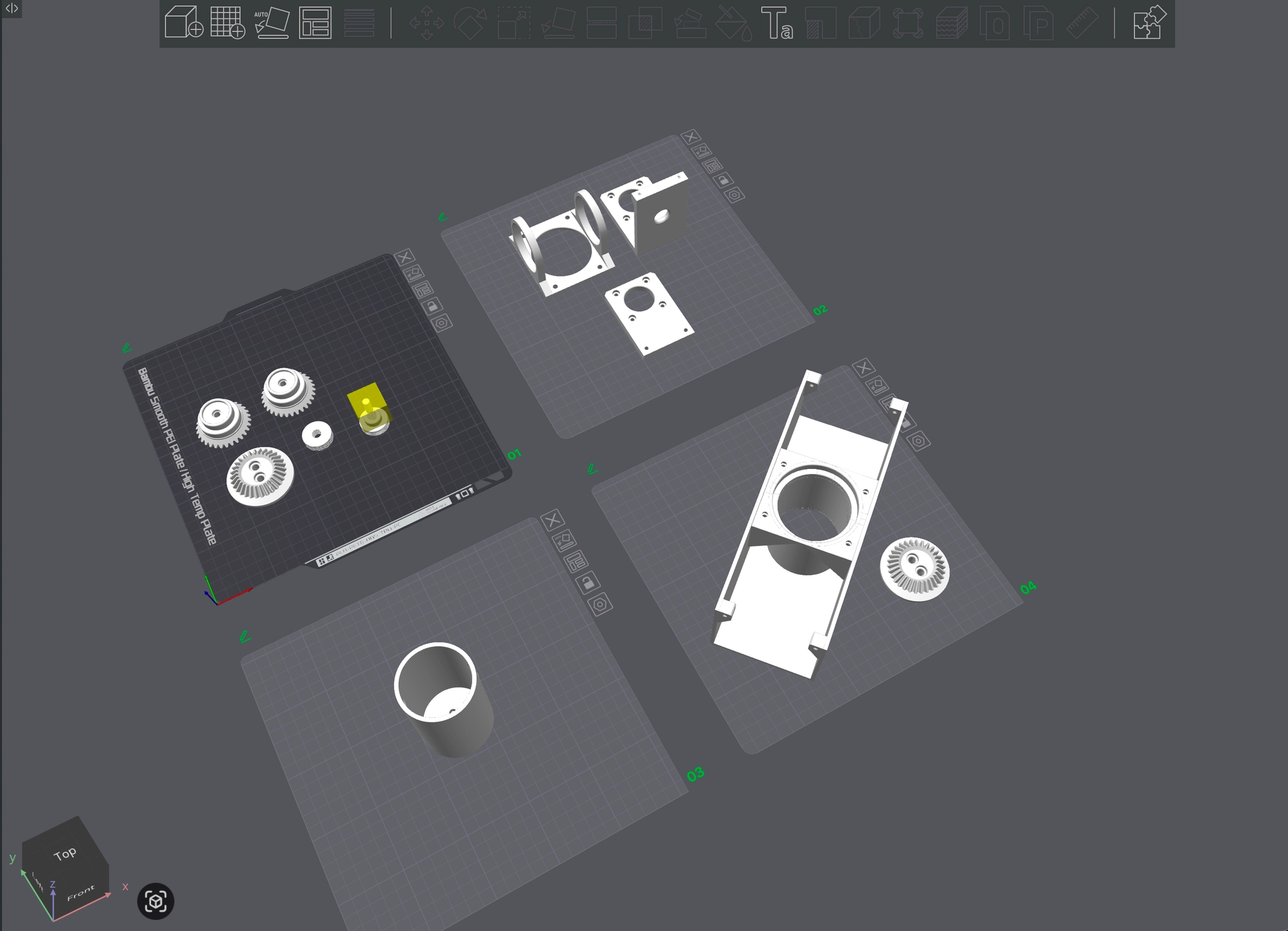
Fabrication Process
Jan 2nd, 1st Prototype
About the Wrist Differential Structure
At the beginning of this project, I was asked to refer to the Rotator from SatNOGs. SatNOGs used a two axis separated motion system, and each axis rotated with a 3D printed worm gear.
Considering the torque that the worm gear can produce, it was a reasonable choice. However, because the parts were 3D printed, we considered the long term durability and sustainability were limited.
For that reason, we chose a wrist differential gear structure to focus on precision and sustainability.

Received Feedback
After sharing the first prototype, we confirmed that it was a suitable form for the direction of the project. However, the prototype couldn't provide enough precision, and there wasn't a box to contain the board and modules, so we decided to move forward with a 2nd prototype.
We also added another goal to the project, which was to create a more accessible design so that the device/station could be reproduced more easily and other developers could try the project without much difficulty.
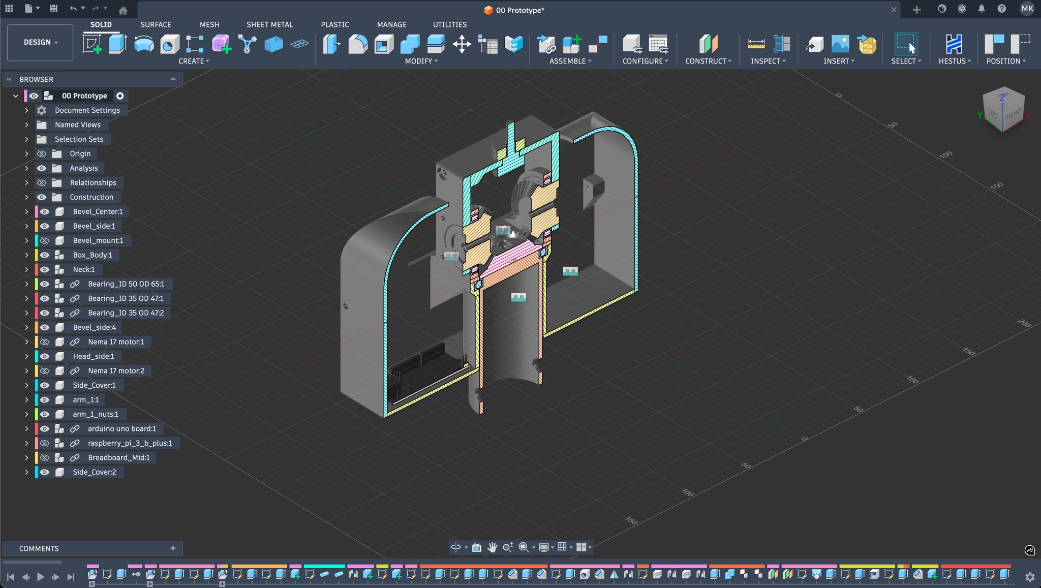
Feb 2nd, 2nd Prototype
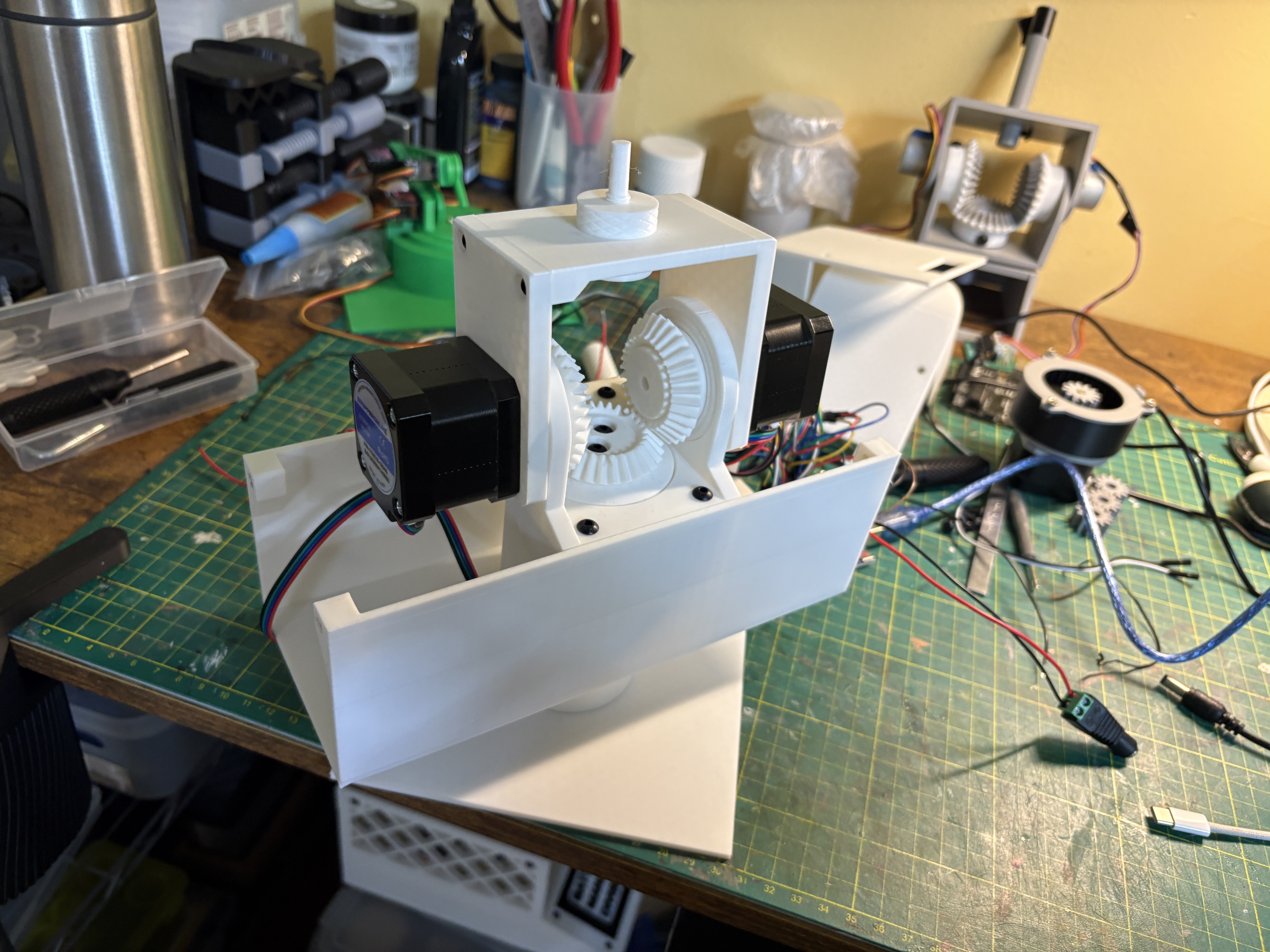
5V stepper motors were replaced with NEMA 17 stepper motors. In addition, the gear module was reduced from 2 to 1.5, which made it possible to apply more gear teeth while keeping the same.
The head part was designed in a modular with antenna installation in mind. In the center of the box, added a cylindrical space that can hold a 5-inch pipe. For better accessibility during development, applied a customized desk stand.
To verify the expected precision, the project moves into the programming stage. Through that process, check whether the torque is sufficient and then apply a coordinate tracking function.

Feb 26th, Optimization & Coordinate Tracking
3D Coordinate Input and Tracking
Succeeded in tracking coordinates within a hemispherical range based on the tracking station. During this process, there were 2 important conditions.
First, when moving toward a target coordinate, the system needed to calculate the shortest path and rotate in the proper direction. In the early stage of development, used atan() to calculate angles. However, atan() couldn't fully determine which quadrant the coordinate was in and which direction it should move from its current position. After learning about atan2(), was able to determine the optimal direction of movement when calculating angles.
Second, when moving from point to point, the z-axis and x-axis needed to rotate at the same time so the tracking station could reach the destination without extra motion. Because of the wrist differential structure, the rotation of the L and R motors affects both axis at the same time. In the early stage of development, controlled the rotation direction and number of revolution of each motor, so diagonal movement was limited. To solve this, I calculated the final combined revolution value whenever a target point was selected. As a result, I was able to create smooth motion through simultaneous 2 axis operation.
Mar 4th, With GUI & Leap Motion 2
I don't think it is good UX to turn on the Arduino IDE and Serial Monitor for the operation. The final goal is to control it through a separate web interface or app, but as an intermediate step, I created a GUI using TouchDesigner.
The system works by applying coordinates with sliders. In addition, to expand the possibilities of the project, I also experimented with hand tracking using Leap Motion 2.
Mar 14th, Enhance Hand Tracking
Modified the system to repeatedly track the position of the hand within certain intervals. This was part of an optimization process for the original goal, continuous satellite coordinate tracking. Through this process, I confirmed that the tracking interval needs to be improved with consideration for the motor rotation time.
Component List
Stepper Motors
NEMA 17 *2
Driver Module
A4988 Driver *2
Board
Arduino Uno R3 *1
Power Supply
12V Power Supply *1
5V Power Supply *1
Extra Research & Experiment
Attempts made to further develop the project and to solve possible issues.
Jan 16th, Robot Arm IK
Considering Robot Arm
I understand that many different methods can be used to implement the tracking function. To explore beyond the limitations of the wrist differential structure used in this project, I also built a robotic arm based on MG90S servo.
It is true that a robotic arm is more versatile and can operate across a wider range. However, 'accessibility' was also an important part of this project, so I decided not to apply the robotic arm approach because it requires more resources and has a higher level of production difficulty.
Still, depends the target/purpose of tracking or the method of tracking, I believe a robotic arm could also be a possible option.
Jan 15th - Feb 16th, Gearbox for Higher Torque
I used a wrist differential structure to improve the weaknesses of the worm gear used in the SatNOGs Rotator.
But, as a result, it lower the torque.
To solve this problem, it was necessary to test 3D printed gearboxes. All of the gearboxes were designed in Fusion 360.
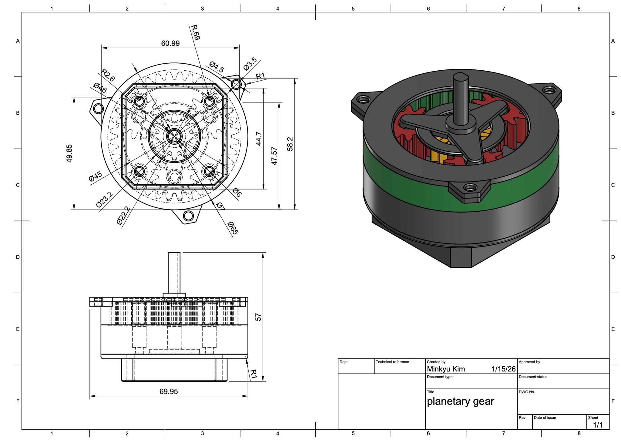
Jan 15th, Planetary Gearbox
Gear Ratio - 1:4

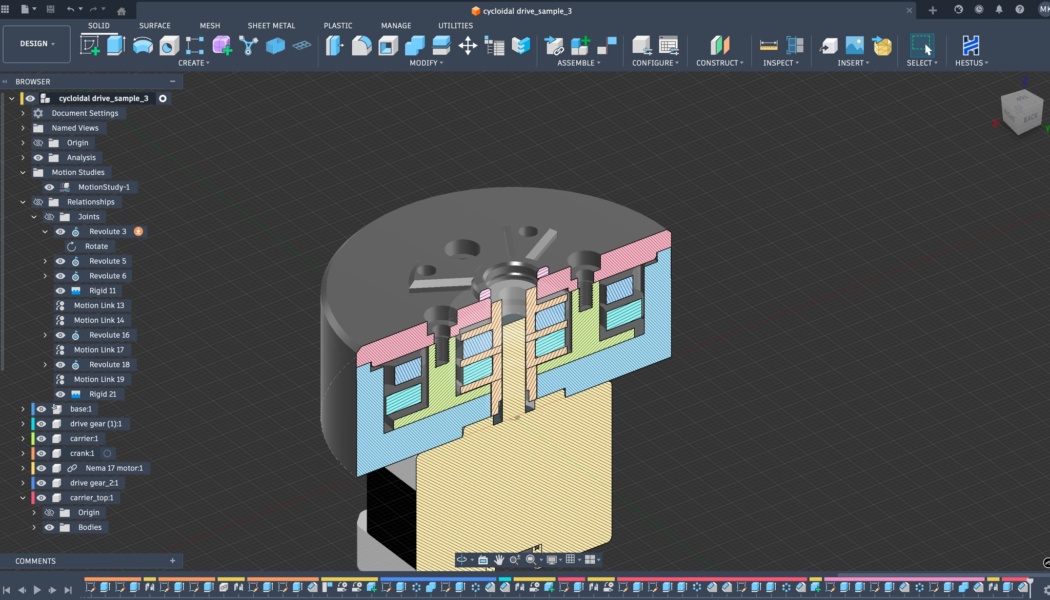
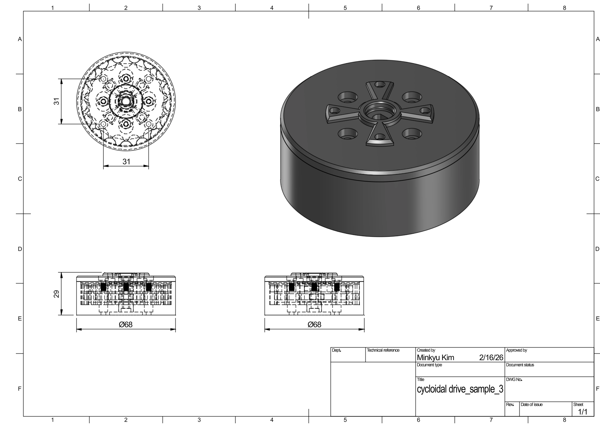
Feb 16th, Cycloidal Gearbox
Gear Ratio - 1:20